|
The first Fresnel Zone clearance required for a link is selected, and a plot of areas where the criteria is achieved are plotted.
More information in the 'How to' on 'fresnel zone coverage'
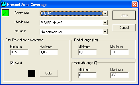
Square indicator - top left
This indicator shows if Clutter or Landcover is included in the prediction.
 |
A red square with a cross indicates that Clutter (Landcover) is not enabled. |
 |
A Green square with a checkmark indicates that Clutter (Landcover) is enabled. |
Select the centre unit. generally here the base station is used. The centre unit can be configured in 'network properties' and the unit location and icon can be set in 'unit properties'
The Centre unit will be used for each bin that is evaluated.
Select the unit that will represent the mobile unit that will be positioned on each waypoint in the route file. The mobile unit can be configured in 'network properties'
The mobile unit will be located on each pint in the waypoint file.
Select a network to wich both units are associated.
First fresnel zone clearance
Here the criteria are set for the 'fresnel clearence'. See 'Fresnel zone' for more information.
Minimum
Minimum value
Maximum
Maximum value
Solid
If checked the displayed result is 'solid'. Default the result will be 'transparent' so the underlying map will shine through.
Color
Select the color of the areas that meet the criteria. see Color selection.
Radial Range (Km)
Min. (Km) / Max. (Km)
The distance from the object between wich is being analysed. (See image below for explanation)
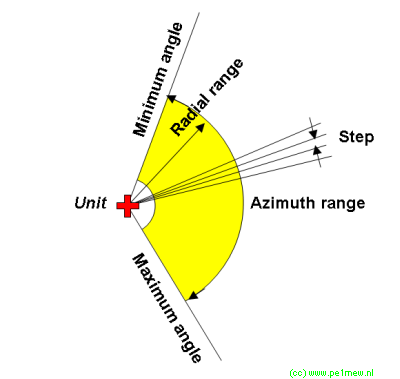
Azimuth Range (degrees)
min / max
The vertical opening angle of the investigated "beam". (See image below for explanation)
|
