
Menu without time delay analysis,

Menu without time delay analysis,
An Interference plot over an area is produced between a wanted and a interfering station, where the minimum signal level and interference margin can be selected and plotted as required.
Interference can be experienced when a unwanted signal is received and this unwanted signal is so strong compared to the wanted signal that it falls within the capture curve or the receiver. In this situation the degradation of the wanted signal can be 'heard'. This is the analysis of the Signal to Interferer (S/I) based on signal strength.
These interference scenario's normally apply to signals of equal phase. In digital radio communications how ever, the delay of a data signal that has equal information but different source like in a simulcast network, can be constructive or destructive. This depends on the 'Time delay' between the wanted and the unwanted signal.
Radio Mobile can analyse based on the time delay between two signals.
More information in the 'How to' on Interference analysis
When checked, the delay in time between the wanted and unwanted signal is taken in account.
Menu without time delay analysis,
Menu without time delay analysis,
This indicator shows if Clutter or Landcover is included in the prediction.
| A red square with a cross indicates that Clutter (Landcover) is not enabled. | |
| A Green square with a checkmark indicates that Clutter (Landcover) is enabled. |
Signal value selection
The analysis result can be expressed in 4 values. Depending on the requirements the value can be choosen and if possible also the range can be set. For more information about the values and the background click on the hyperlinks.
Minimum Signal (>=)
Sets the minimum received signal for proper reception of the mobile receiver.
Minimum S/I (dB)
Sets the minimum difference that should be obtained for proper reception between the wanted and the unwanted signal.
Draw size (pixels)
Sets the size of the bin in which Radio Mobile will calculate the radio path. Please read 'Definitions > Bin' on this topic because performance is affected by this parameter.
Minimum delay (sec)
Sets the minimum delay between the received signal from unit #1 and unit #2.
Required S/I is met
Sets the the color for bins where the S/I criteria is met ( eg. where I < S - S/I margin )
The color can be set using the color button.
S/I is not met, but with acceptable delay
Sets the the color for bins where the S/I criteria is not met but the minimum delay is not passed ( eg. where I < S + S/I margin AND where 'T from #2' < 'T from #1' + t minimum delay )
The color can be set using the color button.
Required S/I is not met
Sets the the color for bins where the S/I criteria is NOT met ( eg. where I > S - S/I margin )
The color can be set using the color button.
Minimum signal is not met
The color for bins where the minimum signal that is specified for the unit is transparent or None.
Mobile Rx Unit
Select the unit that will represent the mobile unit that will be positioned on each waypoint in the route file. The mobile unit can be configured in 'network properties'
In Network
Select a network to which both units are associated.
Use network antenna settings
When checked the antenna's configured in 'Network settings' are overrided for this analysis. In enables to change the antenna pattern with the wanted unit and the Interferer unit.
Draw background
Draws the antenna pattern on the current map with a background
Small
Draws the antenna pattern on the current map window small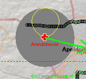 Antenna pattern with a background in the active map window.
Solid
default Radio Mobile displays the coverage result transparent. If checked the result is Solid so you cannot 'look through' the result. The following image shows: Fill area solid using rainbow colors, No Contour color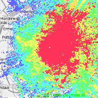
Depending on the mode selected using the 'time delay' check box unit aliases are changed in to 'wanted & Interferer' when 'time delay' is switched of or 'Tx #1 & Tx #2' when 'time delay' is switched on.
Tx Unit
Select the unit that will represent the Tx unit. The unit can be configured in 'network properties'
Antenna pattern
This function is enabled whin in the 'Mobile Unit', 'Use network antenna settings' is unchecked.
If the antenna is selected when the to the unit applied antenna in the 'Network properties' has to be changed on the fly. See 'Antenna pattern' for more information.
Front beam azimuth(degrees)
This function is enabled whin in the 'Mobile Unit', 'Use network antenna settings' is unchecked.
The default direction of the antenna is 0 degrees. Here the direction of the mainlobe of the antenna is set.
Draw pattern
This function is enabled whin in the 'Mobile Unit', 'Use network antenna settings' is unchecked.
If checked the antenna pattern is drawn in the current map window where the analysis is performed
View Pattern
Shows the antenna pattern of the selected antenna and enables to manipulate. See 'view antenna pattern'
Swaps the wanted (Tx #1) and Interferer or (Tx #2)