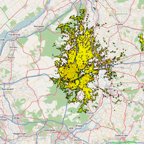
Opens a form in order to initiate visual coverage drawing on a map picture

Visual coverage can be used for line of sight, radar or interception range. It is based on pure geometrical clearance, taking into account the sensor height above ground, the target height above ground (nap of the earth flight), the topography, and the earth curvature.
Earth radius
Visual coverage uses the average earth radius to simulate earth curvature. This explains the difference observed with the radio coverage, where the radio beam tends to bend toward ground.
Observer
Sensor height above ground (m)
This is the height of the source object that is to see, in meters above ground level. Please note that in SRTM both clutter and ground height are combined in one data base. See 'Geodata > Background'.
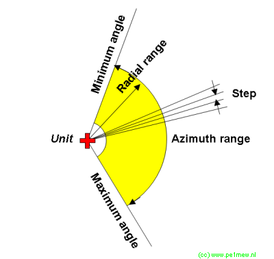
Azimuth range
Minimum / Maximum
The horizontal opening angle of the investigated "beam". (See image below for explanation)
step
The step size of the steps between minimum and maximum. (See image below for explananation)
Radial range
Min. (Km) / Max. (Km)
The distance from the object between wich is being analysed. (See image below for explananation)
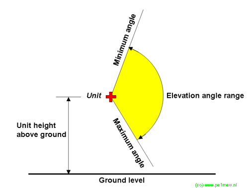
Elevation range angle
min / max
The vertical opening angle of the investigated "beam". (See image below for explananation)
Target
Nap-of-the-eart
-
Fixed altitude
-
Target height above ground (m)
This is the height of the target object that is aimed to reach for in meters abouve ground level. Please note that in SRTM both clutter and ground height are combined in one data base. See 'Geodata > Background'.
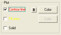
Contour line
Will only display the line of the visual coverage polygon.
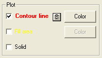
B-button 'Bold'
Selecting the [B] button toggles a Bold or normal line while drawing a contour.
When 'Bold' is selected the Text that represents the result will be bold.
Fill Area
Will only display a transparent filled area of the visual coverage polygon.
Solid
Will only display a transparent solid area of the visual coverage polygon.
color
Choose the color that will be applied to the visual coverage polygon. More information on coloring can be found at ´General functions - color´