|
Fresnel zones are used by propagation theory to calculate reflections and diffraction loss between a transmitter and receiver. Fresnel zones are numbered and are called ‘F1’, ‘F2’, ‘F3’ etc.
There are an infinite number of Fresnel zones, however, only the first 3 have any real effect on radio propagation.
In Radio Mobile Fresnel zones ove a radio path can be analysed in 'Radio Link' and 'RMpath'
What is a Fresnel zone and why is it important?
Fist, what is it? A Fresnel zone is a cylindrical ellipse drawn between transmitter and receiver. The size of the ellipse is determined by the frequency of operation and the distance between the two sites.
First and second Fresnel zones.
How big is it?
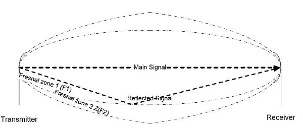
When a radio signal travels between transmitter and receiver, it can travel in several ways. It can go directly between transmitter and receiver (main signal). Signal can reflect off the ground and then carry on to the distant receiver (reflected signal). It can go left or right and be reflected back by a hill (another reflected signal).
Fresnel zone radius describes this reflection in relation to overall radio path length. Figure 2 above shows main and reflected signals and F1 (first Fresnel zone) and F2 (second Fresnel zone). The reflection can happen at any location between the transmitter and receiver. The figure shows the reflection happening at a random location, not the centre of the path.
When a signal is reflected two things happen.
- the phase of the signal reverses and the signal changes in phase by 180º.
- Since the signal is being reflected and not going in a direct line, it travels slightly further to the refection point and then on to the receiver. Therefore, the signal is shifted further in phase, by the difference in path length.
Over a long path, this can amount to 180º or more.
Why is this important? The receive antenna cannot differentiate between a main and reflected signal. They are both on the same frequency. It receives both main and reflected signals. It also receives any other signals within its designed frequency range.
When an antenna receives a main signal and a reflected signal, the 2 signals will combine and add together at the antenna. If they are 360º shifted (in phase), there is no issue. However, if the signals are 180º apart (opposite phase), they will cancel and the receiver will receive nothing.
Fresnel Zone 1 (F1)
The first Fresnel zone radius is calculated so that the difference in path length between the main signal and a reflected signal from the F1 radius distance is 180º. A reflected signal shifted by 180º of path distance plus 180º from the actual reflection point totals 360º of phase shift. The 2 signals, main and reflected, arrive at the antenna 360º apart or in phase. They will add together and not affect receiver performance.
This reflection phase shift can happen anywhere from the calculated Fresnel zone “tube”, properly known as an ellipse.
Fresnel Zone 2 (F2)
The second Fresnel zone radius is calculated so that the path length difference between the main and reflected signals from the second Fresnel zone tube is 360º.
This is critical, since a reflected signal has an automatic 180º phase shift plus the path length difference of 360º equals a phase shift of 540º. 540º and 180º are the same phase shift in mathematics and the 2 signals will cancel, leaving no signal at the receiver.
The second Fresnel Zone, F2, is the zone of reflection that is not wanted when designing a radio path.
Fresnel Zone 3 (F3)
The third Fresnel zone has a path length difference of 540º. Add this to the 180º reflection shift; the total is 720º, and the 2 signals are in phase.
Fresnel Zone Effect
The net result is that Even numbered Fresnel zones incur a 180º signal reflection. These are detrimental to radio propagation. Odd numbered Fresnel zones incur a 360º phase shift and have no effect. Odd numbered Fresnel zones are the “good guys”.
The effect of these reflections in mobile operation can be experienced near the extreme end of coverage of a repeater for example.
What is heard in the receiver is a rapid increase/decrease of signal, often called “picket fencing”. The rapid increase and decrease of signal from a moving radio or vehicle is called Rayleigh fading. It is a direct result of Fresnel zone reflections coming and going as the vehicle moves down the highway.
Point to Point Radio links
Point to point radio links are discussed later in this paper, however, it is worth noting a common design trick for point-to-point links.
Since the F2 zone is detrimental to receive signal level, antenna heights are often selected so that F1 is an unobstructed path and F2 is obstructed by a hill or the earth bulge along the path.
Any 180º reflected signals along the F2 zone are attenuated by the hill or the earth and do not reach the receive antenna to interfere and cancel the main receive signal.
Fresnel Zone Radius and Earth Clearance

Fresnel Zone Radius and Earth Clearance
The diameter of the Fresnel Zone (half the diameter is the radius) of the elliptical cylinder can be calculated. The important component of Fresnel Zone Radius is the clearance between the Fresnel zone cylinder and the surface of the earth. As shown in Figure 3, the Fresnel zone radius and Fresnel zone earth clearance are shown.
If the ratio of:
Fresnel zone earth clearance / Fresnel zone radius
is greater than 60%, the radio path is considered “clear, line of sight” and incurs no diffraction loss.
This understanding of Fresnel zones and their effect assists in understanding how and why radio coverage can be predicted using mathematics and now, computers.
Portions of this text are provided by Brian Henderson and can also be found in his Program Operating Guide.
|
