File file Select the file name of the antenna and so the antenna type. Antenna files are stored in the antenna folder. Antenna patterns are described in 'antenna .ant file format'
Front beam azimuth (degrees) The default direction of the antenna is 0 degrees. Here the direction of the main lobe of the antenna is set.
Front beam gain (dBi) Gain of the front beam. The gain is expressed in dBi (dB relative to a isotrope antenna) A dipole antenna has a gain of 2.15 dBi and 0 dBd (dB relative to a dipole antenna) It is important to pay attention to the gain when using commercially produced antennas and antenna patterns.
Scale This function enables to change the view of the antennapattern. It will set the scale of the antennapattern in dB
The following actions apply to the displayed antenna pattern. It does apply when the draw button is clicked.
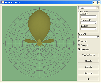
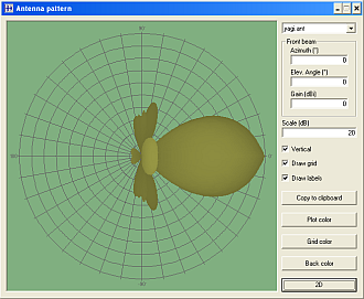
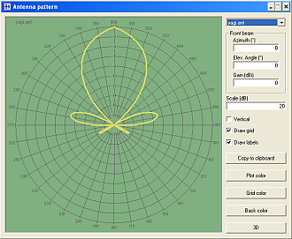
Vertical Toggles display of the horizontal and vertical plane of the radiation pattern. When checked the vertical plane of the radiation pattern is displayed. below are the horizontal and vertical radiation pattern displayed.
When the horizontal plane of the antenna pattern is displayed the main direction (0 or 360 degrees) is heading upwards.
When the vertical plane of the radiation pattern is displayed the antenna is heading to the right where horizontal is 0 degrees. When the antenna is tilted up, this is positive (+). When the antenna is tilted down ( to the ground), this is negative (-) Draw grid Enables the grid to be displayed.
Display grid 'un-checked'
Draw labels Enables the labels to be displayed. This applies to all text in the antenna pattern window.
Display labels 'un-checked'
Copy to clipboard Copies the current displayed antenna pattern, grid, and labels as a image to the clip-board.
Plot color Select the color of the plot that represents the antenna pattern. color selection is described in 'color'
3D Toggles display of the selected horizonal or vertical plane of the radiation pattern.
The images below display the horizontal and vertical plane of the antennapettern in '3D mode'
Cursor Information
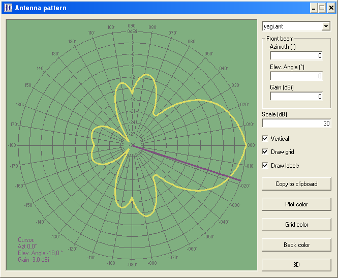
When clicked in the antenna pattern window on or near the radiation pattern a heading line is drawn from the centre to the position clicked. Now the line displays the angle under which the antenna pattern is investigated.
The following image displays the Antenna Pattern menu with the cursor at the -3dB point.
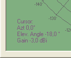
In the bottom-left corner the information is displayed for this cursor position.
Keyboard useage
When using the information from the antenna pattern the [shift-right arrow] key will increase the angle at which the information is displayed by one degree. The[shift-left arrow] key will decrease the angle at which the information is displayed by one degree


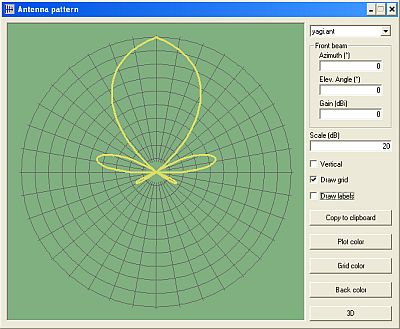 Display labels 'un-checked'