Radio planning starts with a linkbudget. Every individual parameter of the system definition that is applied to the unit is derived from the linkbudget. Also the planning goals are held by the linkbudget.
Because of this a simple explanantion of a linkbudget is given.
 For this explanation I use a recitation that I held for the local amateurradio group of the VERON in Maastricht. The explanantion about Linkbudgets is also used in a recitation about radioplanning. The values are taken from a 70cm repeater near Maastricht: PI2MST.
The linkbudget limits the distance that a radio signal can travel at wich the required service availabilty is reached.
To be able to calculate the value and visualise the result in Radio Mobile we need more detailed information. Genarally there is a situtation where a central transmitter is having contact with a mobile or a hand held radio. But linkbudgets are also used in poit to point links. In this example we use a base station and a hend held portable.
specifications of the repeater.
- Phone repeater at 430.075 MHz
- TX: ~ 10 Watt = 40 dBm
- RX: ~ 0,15 µV = -124 dBm
at 12 dB Sinad
- TX attenuation 3 dB
- RX attenuation 3 dB
- Antenna gain (dipole) 2,2 dBi
(0 dBd)
|
 |
Specifications of the handheld radio
- THD7
- TX: ~ 5 Watt = 37 dBm
- RX: ~ 0,18 µV = -122 dBm
at 12 dB Sinad
- Antenna gain – 4 dB
- Body loss 6 dB
|
 |
Up- and downlink
With a radiolink it is important that both stations can reach each other. In that cas there is a link balance. In the cas ttha on can hear the other but cannot reach him there is a lin un-balance. This happens when one of teh stations has 1000 Watt and the other just 5 Watt.
This table shows the linkbalans calculation for the described case:
| Downlink |
|
|
Formula |
| TX power |
40 |
dBm |
a |
| Tx attenuation |
-3 |
dB |
b |
| Antenna gain |
0 |
dBd |
c |
| Erp power |
37 |
dBd |
d=a+b+c |
| |
|
|
|
| RX sensitivity |
-122 |
dBm |
e |
| RX antennagain |
-4 |
dB |
f |
| RX Bodyloss |
-6 |
dB |
g |
| minimum RX level |
-112 |
dBm |
h=e-f-g |
| |
|
|
|
| MAPL * |
149 |
dB |
i=d-h |
| |
|
|
|
|
| Uplink |
|
|
Formula |
| TX power |
36 |
dBm |
a |
| TX Bodyloss |
-4 |
dB |
b |
| Antenna gain |
-6 |
dBd |
c |
| Erp power |
26 |
dBd |
d=a+b+c |
| |
|
|
|
| RX sensitivity |
-124 |
dBm |
e |
| RX antennagain |
0 |
dB |
f |
| TX Attenuation |
-3 |
dB |
g |
| minimum RX level |
-121 |
dBm |
h=e+f+g |
| |
|
|
|
| MAPL * |
147 |
dB |
i=d-h |
| |
|
|
|
|
MAPL = Maximum Alowed Path Loss
Some notes on the values in the tables:
- The left coloumns show the 'downlink' from base station to hand held
- The right coloumns show the 'uplink' from handheld to base station
- The RX sensitivity is defined at 12 dB Sinad.
- Antenna gain of the hand held is presumed a 'rubber duck'antenna. These perform badly so a negative gain is assumed.
- Body loss is the loss that the body introduces on a hand held device when worn on the body (eg. Belt)
The coverage of the repeater
With the help of Radio Mobile we now can calculate the coverage of the repeater. When we use the linkbudget we know that the hand held radio can receive the repeater at a minimum field strenght of -112 dBm measured in a dipole antenna.
Now we set in Radio Mobile the target treshold at -112 dBm:
This gives the following result. The blue areas are the areas where the downlink signal signal is available >= -112 dBm.
Linkbalance
The result of our calculation is that the MAPL for the downlink 2 dB more is than the uplink. this is caused by the difference in transmit power. In this case there is link-un-balance.
In the case that we increase the transmit power of the base station the link-un-balance increases:
| Downlink |
|
|
Formula |
| TX power |
41.8 |
dBm |
a |
| Tx attenuation |
-3 |
dB |
b |
| Antenna gain |
0 |
dBd |
c |
| Erp power |
38.5 |
dBd |
d=a+b+c |
| |
|
|
|
| RX sensitivity |
-122 |
dBm |
e |
| RX antennagain |
-4 |
dB |
f |
| RX Bodyloss |
-6 |
dB |
g |
| minimum RX level |
-112 |
dBm |
h=e-f-g |
| |
|
|
|
| MAPL * |
151 |
dB |
i=d-h |
| |
|
|
|
|
| Uplink |
|
|
Formula |
| TX power |
36 |
dBm |
a |
| TX Bodyloss |
-4 |
dB |
b |
| Antenna gain |
-6 |
dBd |
c |
| Erp power |
26 |
dBd |
d=a+b+c |
| |
|
|
|
| RX sensitivity |
-124 |
dBm |
e |
| RX antennagain |
0 |
dB |
f |
| TX Attenuation |
-3 |
dB |
g |
| minimum RX level |
-121 |
dBm |
h=e+f+g |
| |
|
|
|
| MAPL * |
147 |
dB |
i=d-h |
| |
|
|
|
|
MAPL = Maximum Alowed Path Loss
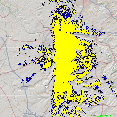
From this we can conclude that a simple increase of power at a base station will do no good because the uplink is not improved to compensate for the increase of power in the downlink Radio Mobile can easily display the link unbalance.
The blue color displays the coverage range of the downlink. The yellow color displays the coverage range of the upnlink.