|
 This function can be call using the [F3] key. This function can be call using the [F3] key.
Where the performance of a single Unit coverage to a defined mobile Unit is performed in a radial sweep manner. Azimuth covered ,and radial range of the plot can be specified.
More information in the 'How to' on 'Radio coverage' and 'Single polar'
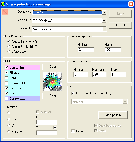
Square indicator - top left
This indicator shows if Clutter or Landcover is included in the prediction.
 |
A red square with a cross indicates that Clutter (Landcover) is not enabled. |
 |
A Green square with a checkmark indicates that Clutter (Landcover) is enabled. |
Centre unit
Select the centre unit. generally here the base station is used. The centre unit can be configured in 'network properties' and the unit location and icon can be set in 'unit properties'
Mobile Unit
Select the unit that will represent the mobile unit that will be positioned on each waypiunt in the route file. The mobile unit can be configured in 'network properties'
Network
Select a network to which both units are associated.
Link Direction
Here the to be calculated path is chosen:
- Centre TX - Mobile RX (Downlink)
- Centre RX - Mobile TX (Uplink)
- Worst case (the worst link of both up- and downlink)
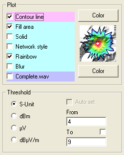
Plot
Here the presentation of the result is configured. While configuring the plot settings, the way the result will be displayed is shown beside the check-boxes. More information abou the various settings and combinations in 'General - Coverage plot types'.
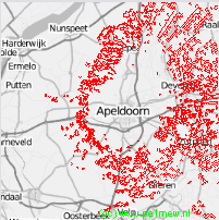
Contour line
If checked the polar coverage result will be have the contour colored. The color can be set using the color button. See Contour line in 'General - Coverage plot types'.
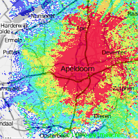
The following image shows: No fill area, Contour colored red:
Fill area
If checked the polar coverage result will be have the fill area colored. The color can be set using the color button. See Fill area in 'General - Coverage plot types'.
Fill area - Network Style
default Radio Mobile displays the coverage result in network style. Network style is configured in File > Network properties > Style. More information can be found at "How to > Use Network Style"

Fill area - Solid
default Radio Mobile displays the coverage result transparent. If checked the result is Solid so you cannot 'look through' the result. See 'Solid' in 'General - Coverage plot types'.
The following image shows: Fill area solid using rainbow colors, No Contour color
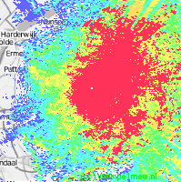
Fill area - Rainbow
If checked the polar coverage result will be have the fill area Colored in a rainbow according to the set colors in Rainbow color. There are 12 steps that can be configured to your need. These steps are 10 equally divided steps (from 2 to 11) from the 'from' value (see below) to the 'to' value (see below). step 1 is x < 'from' and step 12 is x > 'to'.
More information in 'General - Coverage plot types'. The color palette can be set using the color button.
The following image shows: Fill area transparent using rainbow colors, No Contour color
Blur
If checked the coverage result is 'blured'. See 'Blur' in 'General - Coverage plot types'.
Complete.wav
If checked Radio Mobile plays the file 'complete.wav' when the operation is finished.
Treshold
The analysis result can be expressed in 4 values. Depending on the requirements the value can be chosen and if possible also the range can be set. For more information about the values and the background click on the hyper links.
Auto set
If checked Radio Mobile will choose the best value based on the result.
From and To
There are 12 steps that can be configured to your need. These steps are 10 equally devided steps (from 2 to 11) from the 'from' value (see below) to the 'to' value (see below). step 1 is x < 'from' and step 12 is x > 'to'.
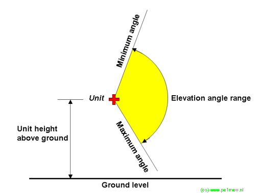
Radial Range (Km)
Min. (Km) / Max. (Km)
The distance from the object between which is being analysed. (See image below for explanation)
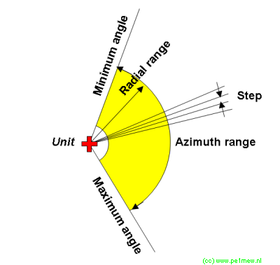
Azimuth Range (degrees)
min / max
The vertical opening angle of the investigated "beam". (See image below for explanation)
Antenna pattern
Here the antenna is selected when the to the unit applied antenna in the 'Network properties' has to be changed on the fly. See 'Antenna pattern' for more information.
|
