|
 This function can be call using the [F6] key. This function can be call using the [F6] key.
This feature enables to analyse coverage over a given route.
It can be done either using a single route or multiple routes (Split routes). Routes have to be in the Ozi Explorer .plt format or GPS track files. The Ozi Explorer .plt format route file can be made using the object editor or using external software. A example can be found in 'How to > Calibrate'. Also routes can be made created using a GPS in the GPS track file format.
More information in the 'How to' on 'Route radio coverage'
Edit > Save data
The result of the analysis can be exported in a text file as 'route radio coverage result file' or as a KML file for use in Google Earth. The format is described in 'route radio coverage result file'
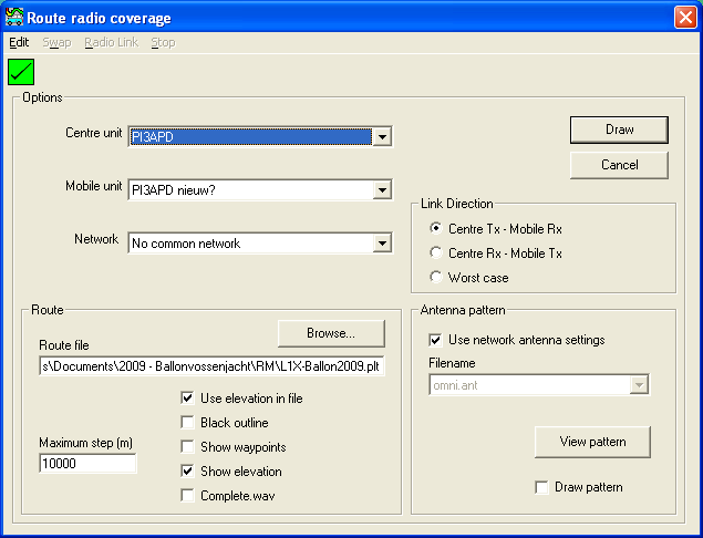
Edit > Options
Initially when selecting the function the window opens the 'Edit > Options' menu. Here the initial settings have to be set to draw the Radio coverage route. This will be displayed on the current map.
Before drawing the route ensure that the route is within the map window boundary's else the route will not be displayed.
Square indicator - top left
This indicator shows if Clutter or Landcover is included in the prediction.
 |
A red square with a cross indicates that Clutter (Landcover) is not enabled. |
 |
A Green square with a checkmark indicates that Clutter (Landcover) is enabled. |
Options
Centre unit
Select the centre unit. generally here the base station is used. The centre unit can be configured in 'network properties' and the unit location and icon can be set in 'unit properties'
Mobile Unit
Select the unit that will represent the mobile unit that will be positioned on each way point in the route file. The mobile unit can be configured in 'network properties'
Network
Select a network to witch both units are associated.
Route
Route file
Select the file that holds the way points that will be analysed. The format of the file can be in 'Ozi Explorer .plt format' or in 'GPS Log .txt format'. Routes can be manually created using the 'Object editor' See 'How to > route radio coverage' for more information.
When using the display function in 'Route RAdio Coverage' the maximum points in a route is 10.000.
Warning: If a route file has more than 10.000 points Radio Mobile will stop half way and not produce any results.
When using the 'Edit - Export' Function in the 'Route Radio coverage' window the number of route points is limited to 32000. Also the interpolation of points between sequential points exeeding the 'maximum step' is disabled when exporting the result file
Maximum step (m)
(This function is only enabled when the result is 'drawn')
Sets the minimum distance between way points over wich Radio Mobile will draw the route line.
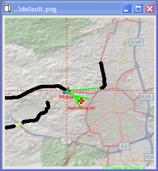
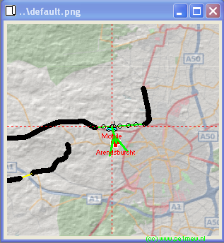
When the route is drawn on the map window a solid line is created between individual way points. When 2 sequential way points are separated over the maximum step value, extra points will be added with the interval set by the minimum step size in between the sequential way points that excess the maximum step size.
Also the radio path is calculated for the by this feature added way points. These calculations are also displayed in the 'Radio route coverage' window.
The following images display a gap in the data that is filled by 500 meter intervals.
Use elevation in file
Toggles the usage of the ground height from the way points file. if not checked the ground height from the DEM is used.
Black outline
Toggles the drawing of a black line around the line that is drawn from way point to way points.
Show waypoints
Toggles the visibility of the individual way points in the file. way points er represented by black circles.
Show elevation
Toggles the visibility of the height in the analysis window.
Complete.wav
Plays the file 'complete.wav' when the operation is finished.
Link Direction
Here the to be calculated path is choosen:
- Centre TX - Mobile RX (Downlink)
- Centre RX - Mobile TX (Uplink)
- Worst case (the worst link of both up- and downlink)
Antenna pattern
Here the antenna is selected when the to the unit applied antenna in the 'Network properties' has to be changed on the fly. See 'Antenna pattern' for more information.
'Draw button'.
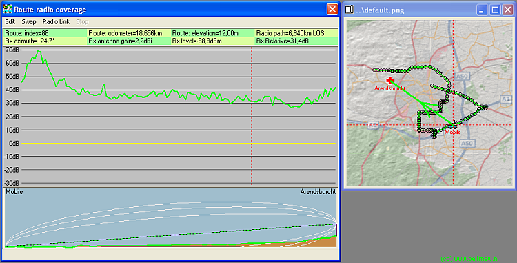
After all preparations are made the 'draw button' is clicked.
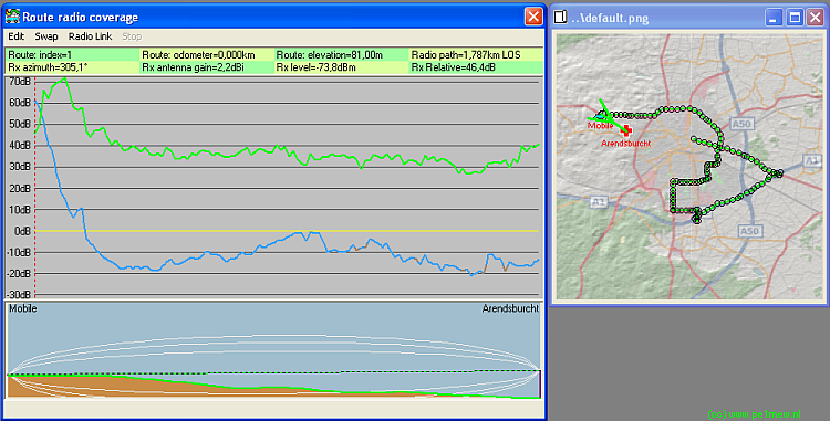
This displays the result of the analysis.
The route is displayed in the 'Radio route coverage' window and on the active map window.
Using te mouse and the arrow keys ( <- and -> ) the result can be analysed. Simultaneously the radio link and direction is displayed in the current map window.
Menu > Swap
Swaps Cente- and mobile- unit for the analysis.
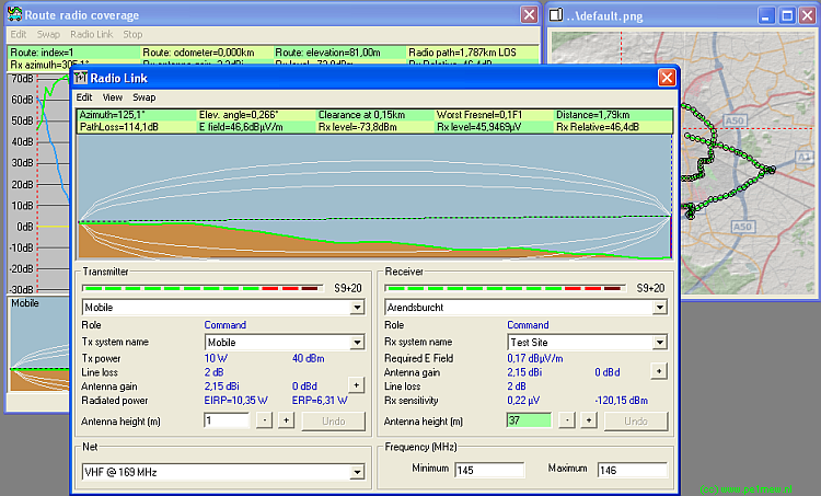
Menu > Radio Link
This menu calls that 'Radio Link' function directly from the 'Route radio coverage' function. The 'Radio Link' function will analyse the selected radio link in the 'radio route coverage' window.
Menu > Stop
Stops the calculation of teh Radio Route coverage.
|
