|
(From Ian G3TVU Quick Start guide, january 2008)
While selecting a single fixed unit Where only one fixed Unit is selected, and the signal levels experienced by a defined mobile unit are calculated.
A click on the toolbar Icon or by opening 'Tools > Radio Coverage > Combined Cartesian' will show this pane, where one or more fixed Units can be selected for the coverage plot. The antenna details are only displayed when a Fixed Unit, Mobile Unit and Network have all been selected.
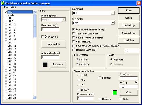
The fixed unit and the mobile unit whose parameters are to be used as the receiver have to be selected. You also have to decide on the Units of measurement and range of signal levels to be displayed, (with the maximum Range to be plotted as an option). It should be noted that the display generated for a Fixed Unit 'Gain' antenna is as if that antenna was pointed towards a particular azimuth - it can be the link direction or defined, i.e. its radiation pattern and direction does apply to the plot. The antenna pattern can be shown on the plot by checking 'Draw' which creates a small drawing of the antenna pattern overlaid at its location aligned with its azimuth. The Mobile Unit however is treated as if it has an 'Omni' antenna, even if in fact a gain antenna is specified in its System. The effect of this is to make a gain antenna on the Mobile Unit always point towards the Fixed Unit for every simulated location.
A 'Combined Cartesian' plot is performed in an X-Y mode, where the signal at each specified pixel area is calculated and plotted. This means that the resolution is constant over the whole screen area, but calculation time is increased. If a 1200x800 pixel area is plotted at 1 pixel resolution it would require 960,000 calculations - with the 'Find Best Sites' feature this is repeated for each Unit in the network, hence the 5 pixel resolution used for the first rough plot of sites, followed by 1 pixel resolution of a selected area to confirm a site location. Once again, if 'Draw Pattern' is selected, a small image of the antenna pattern be drawn.
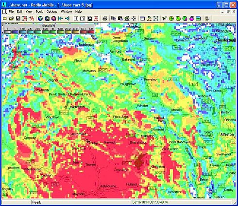
The picture below is the 800x600 pixel Base Cartesian plot at 5 pixel resolution:
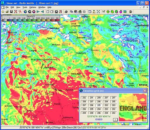
and the following picture at 1 pixel resolution taking 25 times as long to produce:
|
