|
(From Ian G3TVU Quick Start guide, january 2008)
The first Fresnel Zone clearance required for a link is selected, and a plot of areas where the criteria is achieved are plotted.
Detailed Area Coverage Note that it is also possible to perform a defined area plot using any of the above Cartesian plot modes.
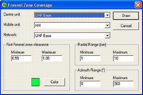
The pane below is obtained from 'Tools > Radio Coverage > Fresnel', where the wanted Fresnel Zone clearance margins are set, units are selected, plot color is selected and the radial and azimuth ranges defined for the plot. This plot was produced using a reduced area UHF version of my 'Base Network' to better display the effects:
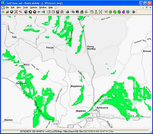
Clicking on 'Draw' then produced the following plot over a greyscale road map:
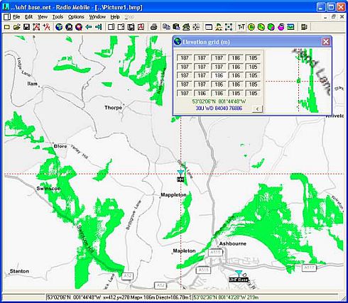
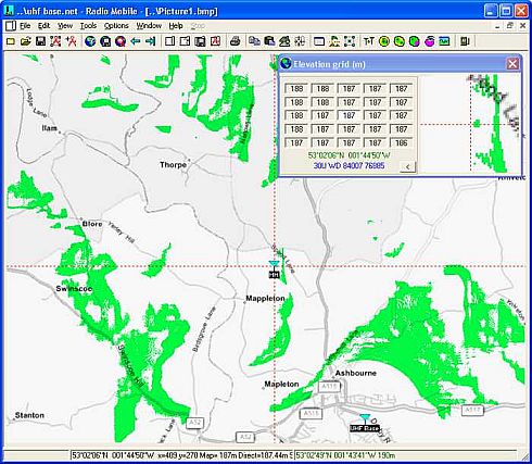
Using the Elevation Grid viewer, the cursor was placed in the small 'acceptable limit' green area shown, and the HH Unit then moved to the cursor position:
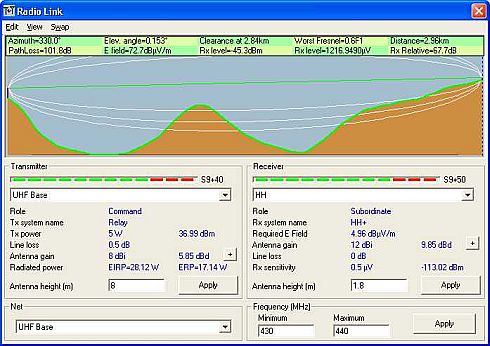
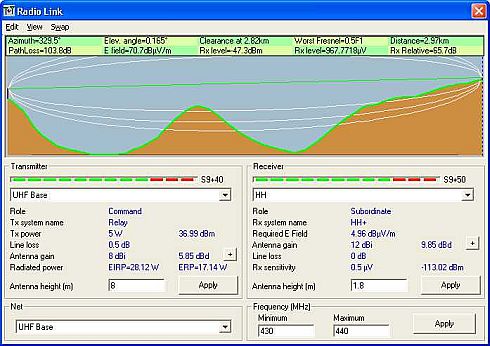
Opening the Radio Link pane then showed the Worst Fresnel clearance of the path was 0.6F1 - which is within the limits set.
Moving the cursor outside the acceptable area as shown in the Elevation Grid viewer, and placing the HH unit at the new location as below:
Then opening the Radio Link pane once more showed this location had a worst Fresnel clearance of 0.5F1 - which is outside the limits set:
|
