|
Radio Mobile - RF propagation simulation software |
|
|
|
|
|
The Profile displays the radio link in 2 D. This includes the earth curvature, round height and Land Cover when enabled.
The link displays the antenna height of both stations. The link from the transmitter unit to the receiver unit is displayed in a direct line from antenna to antenna and the obstructed line.
The Fresnel zones that are relevant for the radio link are displayed as white lines.
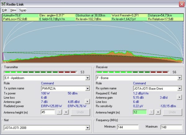
Azimuth
The azimuth of the radio link from the transmitter to the receiver in degrees.
Elev. angle
The elevation angle from the radio link with respect to earth in degrees. A down tilt of the radio link is negative (-).
Obstruction
The distance in Km between the transmitter and the obstruction or Clearance in meters from the radio link to the ground.
Worst Fresnel
The distance to the ground expressed as a factor of F1
Distance
Between the Transmitter and receiver in Km
PathLoss dB
The Pathloss between Transmitter and Receiver in dB.
PathLoss warning
When the limitations of the model have been violated by the settings Radio Mobile will show a warning in red behind the pathloss value. The meaning of these warning can be found at model warnings.
Example: 
E field
At the receiver antenna in dB(uV/m)
RX level in dBm
The RSSI in dBm at the receiver.
RX level uV
The RSSI in uV at the receiver.
RX Relative
The Relative signal in dB with respect to the RX sensitivity.
Transmitter - Receiver
Information about the Transmitter and Receiver planes are at 'Radio Link - Profile'.
|
|
| |
|
|
cmsimple-styles.com template modified by PE1MEW |
