|
Radio Mobile - RF propagation simulation software |
|
|
|
|
|
The details provide a summary of the radio link in text.
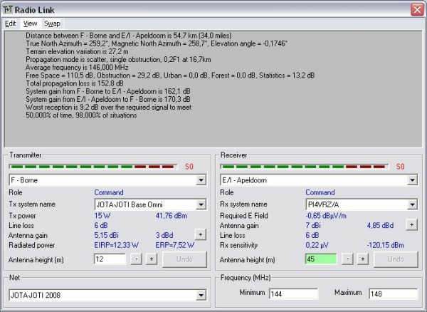
Distance between units
The distance between the TX and RX unit in Km
The Link Azimuth and elevation angle
The Azimuth degrees with respect to True north and magnetic north, and the Elevation angle in degrees with respect to the earth at the transmitter location.
Terrain elevation variation
The variation in terrain elevation in meters.
Propagation mode
These are the results of the propagation model over the radio link.
In this example the mode is "Scatter" and there is one single obstruction of 0,2F1 at 16,7 Km from the transmitter.
Average frequency
The average of the minimum and the maximum frequency used in this simulation and at which the calculation is done.
Free space loss, Obstruction, Urban, Forest, Statistics
The individual values that are calculated in the propagation model in dB.
Total propagation loss
The loss in dB as a result of the calculation using the propagation model between the TX and RX antenna.
System gain TX to RX
Downlink Maximum allowed Path loss (MAPL)
System gain RX to TX
uplink Maximum allowed Path loss (MAPL)
Worst reception
The lowest RSSI calculated on the radio link in dB with respect to the RX sensitivity.
Model settings
Displays probability settings as configured in 'network properties - Parameters'
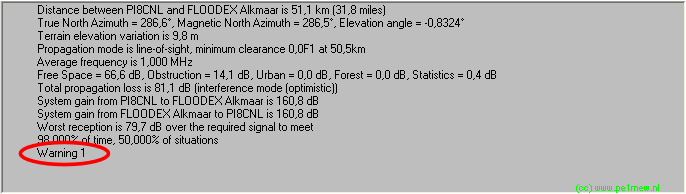
Warning
This message is only displayed when a warning is active.
When the limitations of the model have been violated by the settings Radio Mobile will show a warning in red behind the path-loss value. The meaning of these warning can be found at model warnings.
Example: The warning is in the red ellipse.
Transmitter - Receiver
Information about the Transmitter and Receiver planes are at 'Radio Link - Profile'.
|
|
| |
|
|
cmsimple-styles.com template modified by PE1MEW |
