|
Radio Mobile - RF propagation simulation software |
|
|
|
|
|
The verification of a prediction model starts with collecting survey data.
Before you start collecting the data you have to concider what your objective is because the objective influences the method of collecting survey data. Also the availabale technology will put a limit on what can be done with the collected survey data and what accuracy will be gained.
The common method of RF engineers to collect survey data is to install a fast scan receiver for the aproperiate frequency band on to a drive test vehicle and a test site on a building. The survey vehicle is most of the time a car but in some cases a trolley or a bike. Even a train can be used to carry the equipment.
A survey vehicle can also be used to install the measurement antenna on. Regarding the antenna the following topics have to be addressed:
- Is the antenna calibrated,
- Is the antenna impedance known,
- Is the antenna efficiency factor (K-factor) known,
- Is the radiation pattern of the antenna on the vehicle known,
Quality
The test site you create has to perfom well. To realise this you have to do some verifications:
- Is the VSWR of the antenna OK?
- Is the cable attenuation for the used requency OK?
Radiation pattern
Because we are using a drive test vehicle it is asumed that the vehicle will be used in various directions with respect to the transmitter site. In this case it is requred to know the antenna pattern of the measurement antenna or even better: the antenna pattern is omni-directional.
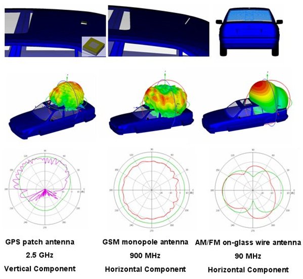
In the following images the effect of the type of antenna and the position of the antenna on the rooftop of the car is displayed.
To be able to complete the linkbudget and use this information in 'Network properties > Systems' the following information has to be registered:
- Receive sensitivity in dBm or uV
- Attenuation of the cable between the receiver and the antenna in dB or dB/m in combination with the length of the cable
- Aditional losses in the system in dB

As you can see the position of your measurement antenna on the rooftop of a car is important.
The best position of the antenna is on the middle of the roof of the car. This is where the two hart-lines drawn over the rooftop from left to right and front to back, cross. This is the best location for your measurement antenna.
Other important objects on your rooftop are: Bars on the left and right side of the rooftop, radio and cellular antennas, and a sun-window. These objects should not be on a rooftop for cars used for drivetests.
If we have avoided these objects the antenna will be the best omi-directio antenna that can be made on a car roof.
As it is with the test site the antenna gain has to be known and fed back in to Radio Mobile. It is best to use a 1/4 lambda antenna on the metal plane of the car roof. This antenna will have a gain of 0 dBd.
The receiver
The receiver used for collecting survey data must be able to output RSSI to a computer. The computer will log the reported values and combine them with the current location wich is captured from a GPS receiver. In some cases it is required to have a 'dead reckoning' function. This function enables to keep accurate locations when the reception of the GPS signal is lost. This happens in tunnels or in urban canyon where the signal is blocked by tall buildings.
There is a lot to say about receivers for collection survey data and not many radio amateurs have these specific equipment available. It is currently out of scope to go in to detail on fast scan receivers.
Overview of to be registered parameters
- Antenna gain in dBd or dBi
For the unit in 'Unit properties' and 'Network properties > Systems' the following parameters have to be registered:
- Antenna height above ground
|
|
| |
|
|
cmsimple-styles.com template modified by PE1MEW |